PLC Programming Fundamentals (Ladder Logic)
Ladder logic looks intimidating until you realize it was built to look like the relay diagrams electricians already trusted. Here is how PLCs actually think, and why ladder logic remains the language of the factory floor.
TL;DR
A PLC is a rugged computer built for the factory floor. It repeats a scan cycle: read inputs, solve the program, write outputs. Ladder logic looks like the relay diagrams electricians already trusted, and patterns like the start/stop seal-in circuit run the world. IEC 61131-3 standardizes the languages.
On this page
Walk into almost any modern factory and you are surrounded by decisions being made thousands of times per second. A conveyor starts when a button is pressed and refuses to start when a guard is open. A filler stops after exactly twelve bottles. A fan keeps spinning for a few seconds after the line halts. Behind nearly all of it sits a small, unglamorous box: the programmable logic controller, or PLC.
For automation technicians and maintenance staff, the PLC is both the most important device on the floor and, often, the most mysterious. The good news is that the core ideas are genuinely approachable. You do not need a computer science degree to read and write the most common PLC language, ladder logic. You need to understand two things: how a PLC thinks, and how to draw your intentions as a ladder.
A computer built for the worst place to put a computer
A PLC is a ruggedized industrial computer. That ruggedness is the whole point. Office computers live in climate-controlled rooms; PLCs live next to motors that vibrate, contactors that spew electrical noise, and air thick with dust and coolant mist. They are engineered to keep running where ordinary electronics would quietly die.
PLCs arrived in 1968 to solve a specific, expensive problem. Before them, machine logic was implemented with banks of physical relays wired together. The logic worked, but changing it meant rewiring the panel by hand, a slow and error-prone job. The PLC replaced that hard wiring with software. Suddenly the same hardware could run completely different behavior just by loading a new program. That single shift is why PLCs took over industrial control and never let go.
Read, solve, write, repeat
The most important concept in all of PLC work is also the simplest: the scan cycle. A PLC does not run your program once. It runs it over and over in a tight loop, typically completing each pass in a few milliseconds.
Each pass has three core stages. First, the PLC takes a snapshot of every input, copying the live state of buttons and sensors into memory. Second, it solves the program logic using that frozen snapshot. Third, it writes the results out to the physical outputs, switching motors and lamps. Then it does housekeeping and starts again.
This read-solve-write rhythm explains a surprising amount of PLC behavior. Because the logic works from a snapshot rather than live wires, results are predictable and repeatable. But it also means a signal shorter than one scan can slip through unnoticed, which is why fast events sometimes need special high-speed inputs. Internalize the scan cycle and most “weird” PLC behavior stops being weird.
Why it looks like a ladder
Here is the clever bit of history. When PLCs were introduced to replace relay panels, the designers did not ask electricians to learn an abstract programming language. Instead they gave them a language that looked exactly like the relay wiring diagrams they already read every day. That language is ladder logic.
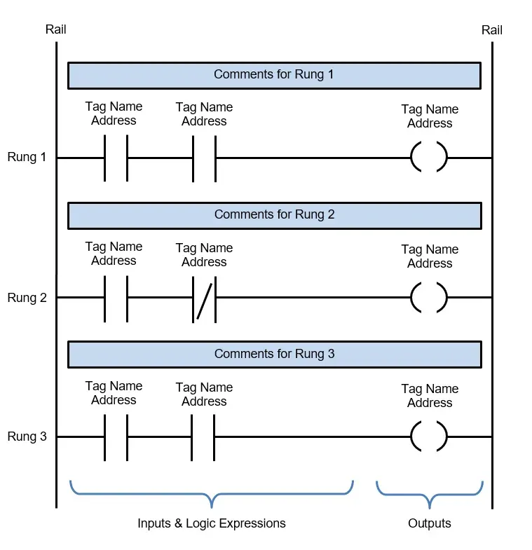
A ladder program has two vertical rails and horizontal rungs between them. You read each rung left to right, imagining power flowing from the left rail toward an output on the right. Conditions are drawn as contacts; results are drawn as coils.
A normally open contact, drawn as –[ ]–, passes that imaginary power flow when its signal is true. A normally closed contact, –[/]–, passes it when its signal is false. An output coil, –( )–, turns on whenever an unbroken path reaches it. Place contacts one after another and you get a logical AND, where everything must be true. Stack them in parallel branches and you get a logical OR, where any one will do. A normally closed contact gives you a NOT. With just those pieces you can express an enormous range of machine logic.
One distinction trips up nearly every beginner: in ladder logic, “normally open” and “normally closed” describe the instruction in the program, not the physical wiring of the device in the field. Keeping those two ideas separate is half the battle.
The pattern that runs the world
If there is one rung worth memorizing, it is the seal-in, also called the latch. It is how you make a machine stay on after you release the start button:
  Start_PB   Stop_PB    Motor
----[ ]--------[/]--------( )----
   Motor       |
----[ ]--------+
Press Start and power flows through the unpressed Stop contact to energize the motor. The motor’s own contact, wired in parallel, then “seals in” the rung, holding the motor on after you let go of Start. Press Stop and the path breaks; the motor drops out and, because the seal-in path is broken too, stays off. This one pattern, dressed up with timers and counters, controls a staggering fraction of industrial machinery.
Standardized, and worth learning properly
Ladder logic is not a vendor quirk. It is one of five languages defined by the international standard IEC 61131-3, first published in 1993, alongside Function Block Diagram, Structured Text, Instruction List, and Sequential Function Chart. That standardization means the concepts you learn transfer across manufacturers, even when the exact button labels and address formats differ.
You can go a long way with the basics. Add timers to handle delays, counters to track quantities, meaningful symbolic tags so the next technician can read your work, and a disciplined commissioning checklist so nothing energizes by surprise. Start with the seal-in circuit, trace it by hand until the power flow is obvious, then build outward. The factory floor will feel a lot less mysterious, one rung at a time.
Key takeaways 5
- PLCs are industrial computers built for harsh environments.
- The scan cycle reads inputs, solves logic and writes outputs, endlessly.
- Ladder logic mimics electrical relay diagrams.
- The start/stop seal-in rung is the most important pattern to learn.
- IEC 61131-3 standardizes ladder and the other PLC languages.
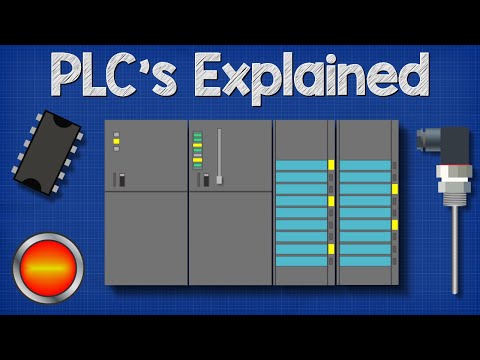
Watch & learn
Frequently asked questions
What is ladder logic?
Ladder logic is a graphical PLC programming language that looks like electrical relay diagrams, with rungs of contacts (conditions) and coils (outputs) between two vertical rails.
What is a PLC scan cycle?
The repeated cycle in which the PLC reads all inputs, executes the program from top to bottom and then updates all outputs, typically in milliseconds.
What is a seal-in (latching) circuit?
A rung where the output's own contact keeps it energized after the start button is released, until a stop condition breaks the circuit, the classic motor start/stop pattern.
Go deeper with the free masterclass
Workshop, PDF handbook and curated resources for “PLC Programming Fundamentals (Ladder Logic)”.
Related articles
AI-Driven Anomaly Detection on the Line
Why catching abnormal behavior in real time is less about the algorithm and more about trust, data discipline, and the cost of being wrong.
Motion Control & Servo Drives
Servo systems feel like dark art until you see the simple logic underneath. Here is the mental model that turns motion control from guesswork into engineering.
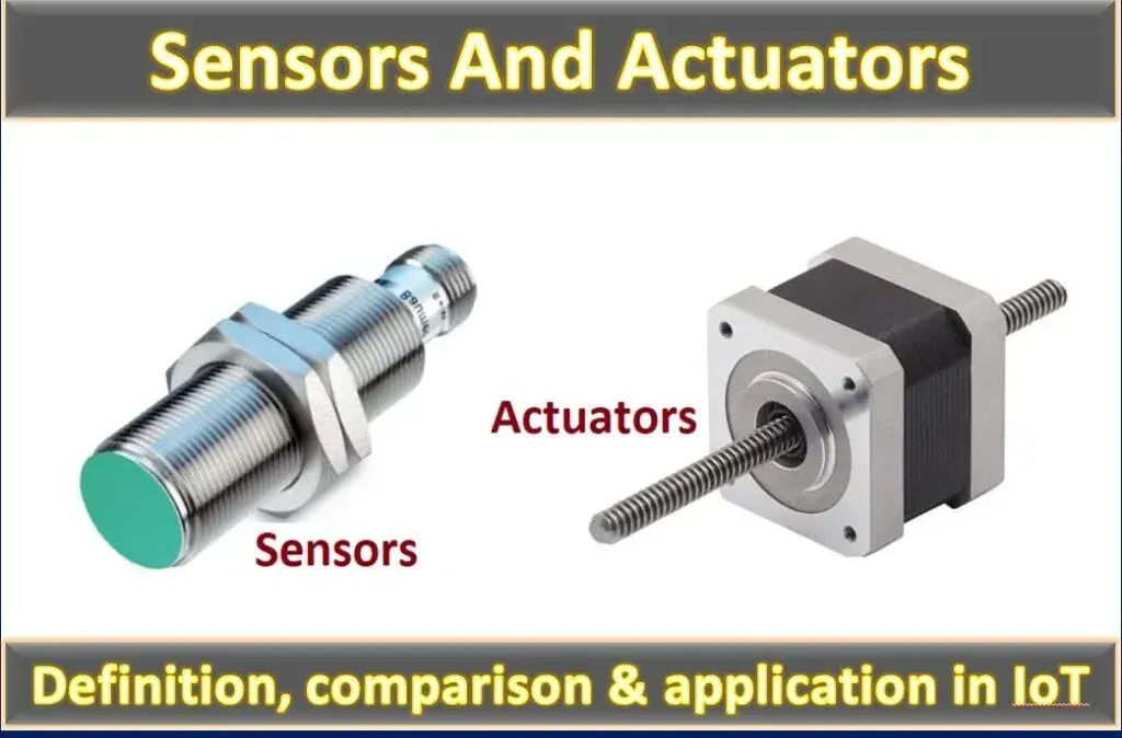
Sensors & Actuators in Automation
Every automated machine runs on the same three-beat rhythm. Learn the sensors that perceive, the signals that carry the message, and the actuators that act, and you can read almost any machine on the floor.
Comments
No comments yet. Start the conversation.