Motion Control & Servo Drives
Servo systems feel like dark art until you see the simple logic underneath. Here is the mental model that turns motion control from guesswork into engineering.
TL;DR
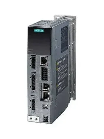
Servo tuning gets blamed for problems usually decided earlier. Start with what the machine must do (move, time, load, precision), choose motor, gearing and inertia ratio carefully, understand the nested current, velocity and position loops, and let a good motion profile do half the work.
On this page
Ask a roomful of automation engineers what makes a servo axis hard, and you will hear the same word over and over: tuning. The motor is bolted down, the wiring is correct, the program runs - and yet the axis buzzes, overshoots, or feels like wet rubber when you push it. Tuning gets blamed because it is the last thing you touch. But in my experience, most “tuning problems” are actually decisions that were made wrong long before anyone opened a gain parameter. The good news is that motion control has a clean underlying logic, and once you see it, the dark art evaporates.
Start with what the machine must do
Every motion problem begins with four numbers: how far, how fast, how heavy, and how often. Distance and time together fix the speed. Speed and time fix the acceleration. Mass and acceleration fix the force. Force and the mechanism fix the torque. That is the whole chain, and it runs on arithmetic you can do on the back of a drawing.
Suppose you must move 300 mm in half a second. With a simple trapezoidal profile split into equal thirds of acceleration, cruise, and deceleration, the distance is just the area under the velocity curve, which works out to peak velocity times two-thirds of the move time. Rearranged, peak velocity is 0.3 m divided by (0.667 times 0.5 s), or 0.9 m/s. On a 10 mm-lead screw that is 90 revolutions per second, which is 5400 rpm at the motor. Right there, before choosing anything, you know you need a motor that spins fast.
Acceleration follows: 0.9 m/s reached in a sixth of a second is 5.4 m/s squared. Move 20 kg at that rate and you need 108 newtons just to accelerate the mass, plus whatever friction adds. Push 148 N through a 10 mm screw at 90 percent efficiency and you are asking the motor for about a quarter of a newton-metre at peak. None of this is exotic. It is high-school physics applied honestly, and it tells you the motor’s job before you go shopping.
The hardware decision is the real tuning
Here is the part people skip. The single biggest predictor of whether an axis tunes easily is the inertia ratio - the load inertia as the motor feels it through the mechanism, divided by the motor’s own rotor inertia. Keep that ratio somewhere between roughly one-to-one and ten-to-one and the axis almost tunes itself. Let it balloon to fifty-to-one because someone picked a tiny motor to save money, and you will spend days fighting resonance and instability that no clever gain set can fully cure.
The same goes for matching motor type to the task. A stepper is a wonderful, cheap, open-loop positioner at low speed, but its torque collapses as it spins up, and in open loop it never tells you when it has stalled. A servo holds torque flat across its speed range and, with its encoder, guarantees the move - at a price. An induction motor on a variable-frequency drive is the right answer when you care about adjustable speed, not precise position, as with pumps and conveyors. Choosing the wrong family is a mistake you tune around forever.
Loops inside loops
When you do get to tuning, the structure is not mysterious. A servo drive runs three nested loops: a fast current loop in the middle, a velocity loop around it, and a position loop around that. Each outer loop hands a command to the one inside it. The position loop asks for a velocity; the velocity loop asks for a torque; the current loop delivers it. The iron rule is that each inner loop must be faster than the one outside it, so you tune from the inside out. A sluggish velocity loop dooms the position loop no matter what you do to it.
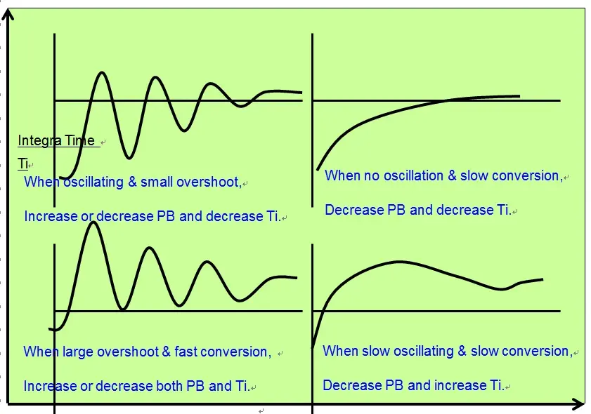
The control law in each loop is the familiar PID. Proportional gain reacts to the error you have now and makes the axis stiff. Integral gain accumulates past error and erases the stubborn little offset that proportional alone leaves behind. Derivative gain reacts to how fast the error is changing and adds damping, though it amplifies noise, so many engineers use it sparingly. Raise proportional until the axis is crisp but not buzzing, add integral until the offset disappears but before it starts hunting, and stop.
Let the profile do half the work
There is one more lever that quietly solves problems people attack with gains: the motion profile. A trapezoidal profile switches acceleration instantly at its corners, which means jerk - the rate of change of acceleration - spikes to infinity for an instant. The machine feels that as a knock, and flexible structures ring like a bell afterward, stretching out settling time and wearing parts. An S-curve profile ramps the acceleration smoothly instead, capping jerk. It costs a sliver of cycle time and pays it back in quiet, accurate, durable motion.
Better still, because the controller knows the whole profile in advance, it can feed the expected velocity and acceleration straight into the loops as feedforward. That cancels most of the following error before feedback ever has to react. The result is an axis that tracks its command tightly without aggressive, twitchy gains. Smooth commands and good feedforward are the secret behind systems that look effortlessly precise.
The mindset
None of this requires genius, just order. Define the move in numbers. Choose hardware that respects those numbers, with margin and a sane inertia ratio. Trust the encoder before the power loops. Tune inside out, one parameter at a time, reading the symptoms instead of guessing. Shape a profile that the mechanism can live with. And wrap the whole thing in an independent safety layer that can always bring the axis to a safe stop.
Do that, and the dark art turns into a checklist. The axis comes up fast, runs smooth, and stays reliable - and the next person who inherits it will think you were a wizard. You will know it was just physics, in the right order.
Key takeaways 5
- Most tuning problems are really sizing and design decisions.
- Start from the motion the machine must perform.
- Inertia ratio and mechanics matter more than gains.
- Servo drives use nested current, velocity and position loops.
- Smooth motion profiles reduce the work the loops must do.
Watch & learn
Frequently asked questions
How does a servo motor system work?
A servo drive controls the motor using feedback from an encoder, adjusting current to reach a commanded position, speed or torque through nested control loops.
What is inertia ratio in servo sizing?
The inertia ratio compares the load's reflected inertia with the motor's rotor inertia. A ratio that is too high makes the axis harder to control; gearing can reduce it.
What is an S-curve motion profile?
An S-curve profile ramps acceleration up and down smoothly, limiting jerk, which reduces vibration and mechanical stress compared with a simple trapezoidal profile.
Go deeper with the free masterclass
Workshop, PDF handbook and curated resources for “Motion Control & Servo Drives”.
Related articles

AI-Driven Anomaly Detection on the Line
Why catching abnormal behavior in real time is less about the algorithm and more about trust, data discipline, and the cost of being wrong.
Control Loops & PID Tuning
Three terms, one loop, and the quiet art of making a process behave.
PLC Programming Fundamentals (Ladder Logic)
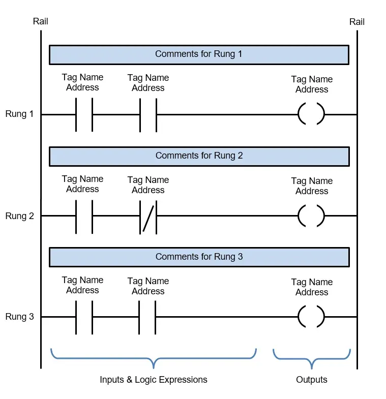
Ladder logic looks intimidating until you realize it was built to look like the relay diagrams electricians already trusted. Here is how PLCs actually think, and why ladder logic remains the language of the factory floor.
Comments
No comments yet. Start the conversation.